How to 3D-print the Rubin Model base at home

Bill of Materials
0.75kg 1.75mm 3D printing filament (PLA, ABS, ASA - PETG is untested)
8 M3x8 Button-Head Cap Screws (BHCS)
(Optional) 8 M3x5x4 Heatset Inserts (4mm deep, 5mm wide)

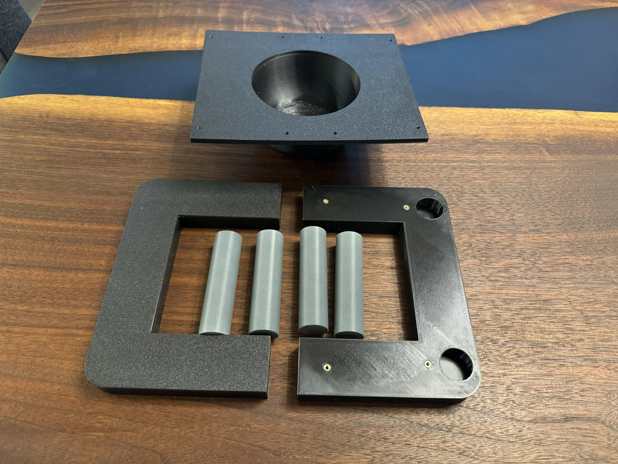
Printed Parts
1 Tray Insert (bowl)
2 Top Frame halves
4 Legs
Printing Guidelines
0.4 or 0.6mm nozzle
0.2 to 0.3mm layer height
15% Cubic infill
3 Perimeters/Wall loops
5 Top and Bottom Layers
Bed size required: Minimum 220mm x 205mm
Multicolor/Multibody: Optional
Supports: Enable supports on Tray Insert only and only on build plate.
Recommended Slicer Software: OrcaSlicer
Download STLs/OrcaSlicer Project: rubin_model_base.zip
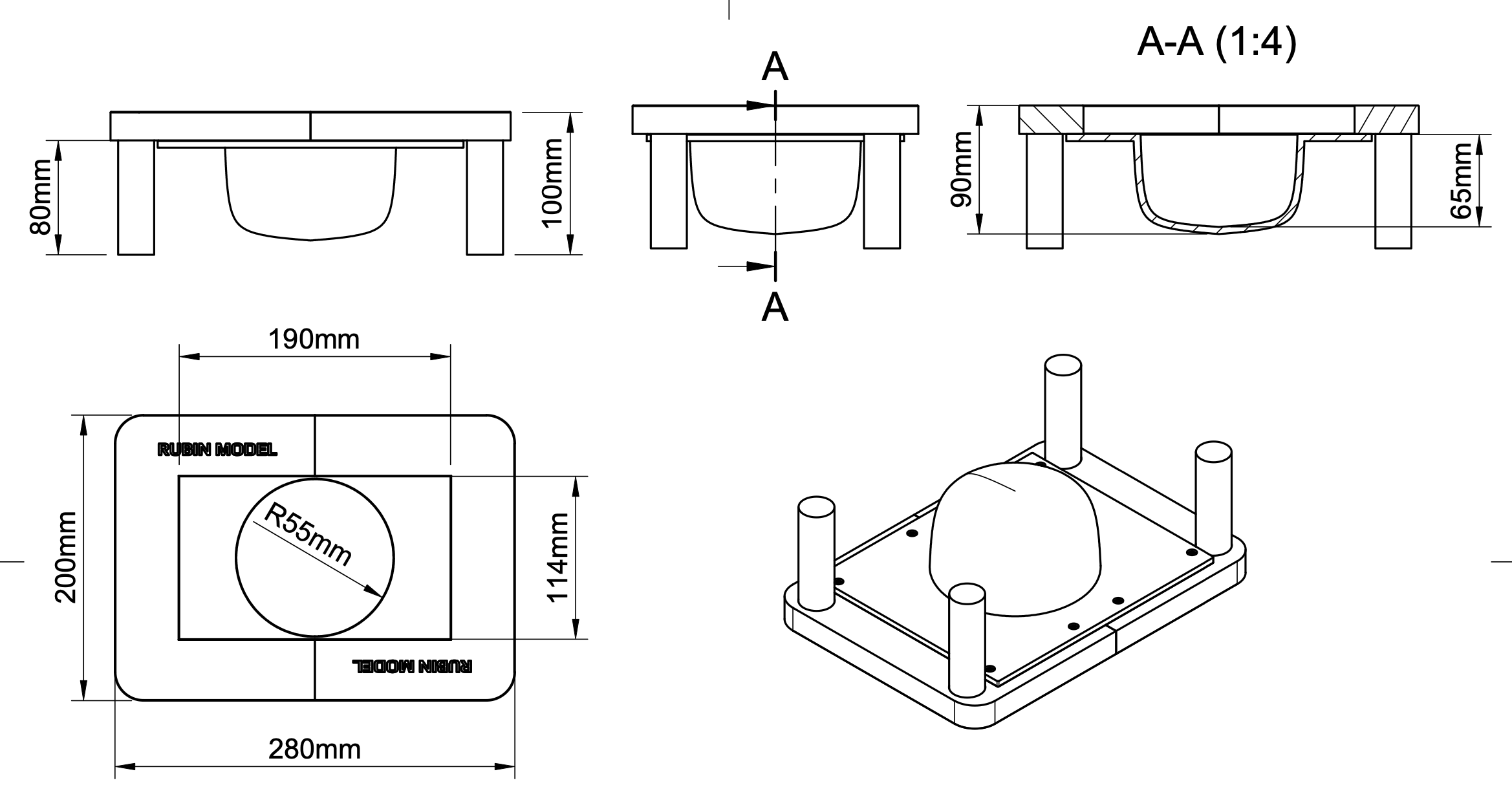
Technical Drawing: rubin_model_diagram.pdf
Assembly - Self Sourcing
The top frame can accept M3 heatsets for more durable repeated assembly and disassembly. If installing heatset inserts - the top frame halves have 8 total M3 threaded heatset inserts, which are installed by melting them into the frame half using a soldering iron.
A version of the top frame is also available where the screws will form threads into plastic. It will be a tight fit, but do not overtighten and strip out the plastic.
Secure the tray insert to the frame halves with (8) M3x8 Button-Head Cap Screws (BHCS). Insert the legs into the holes in the bottom of the frame halves, they are held in place by friction. If they are a little loose, you can wrap them with a thin layer of masking tape (or if self-printing, scale the leg model up a little bit in your slicer software and reprint.)